Authors: Savita Singh, Rakesh R Shankar,
Siraj Bhattacharya, Dr. Harvey Blumsack
Power Transmission Business, Sterlite Technologies Limited
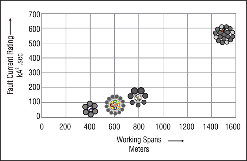
Even after more than 1,00,000 km of supplies by various manufacturers worldwide, the Stainless Steel Optical Unit still has various application issues pertaining to different utility requirements, the major issues encountered by them have been enumerated like bulkiness of the product, less conductivity and low/moderate fault current ratings. These issues have been sorted by an innovative method of cladding the Stainless Steel Tube with Aluminum to create a robust and ideal design and ensuring a higher metallic cross sectional area for a given diameter.
Sterlite produces different configurations of OPGW to provide the most cost effective balance between specific technical, installation and application requirements. Four distinctly different constructions are offered by Sterlite as per our official brochure to satisfy the following three primary functions OPGW serves along a transmission or distribution line:
- Shield phase conductors from lightning strike
- Carry current during unbalance or short circuit events
- House and protect the optical fibers
Quality Aspect
It is important to select a cable manufacturer with design and manufacturing capability to furnish a reliable cable to assure dependable ground wire/ telecommunication system that will operate for many years without problems.
Sterlite designs its Optical Ground Wire, selects its material, produces and tests the cable in concert with statistical studies to perform without problem over its design lifetime of longer than 30 years. Cable manufactured by Sterlite meets or exceeds the requirement of IEEE 1138, “standard for testing and performance to Optical Ground Wire for use on electric utility panel lines” November 2009. IEEE specification 1138 imposes testing to assure that OPGW has been made designed and tested to meet certain requirements which may or may not attest to the long term reliability of the cable.
The Optical Unit
Sterlite produces a number of different configuration of OPGW to offer trade – off between specific technical and installation requirements. However, the best performing configuration of optical unit is one that provides a stainless steel buffer tube that contain the optical fibers, around which is applied an aluminium pipe. Cable addresses application concerns regarding weight and diameter as well as crush strength and moisture. Fibres have maximum protection from lightning effects, short circuit and tensile loading.
The stainless steel tube utilizes grade type 304. Type 304 was developed to provide high strength and high modulus as well as superior anticorrosion properties. Sterlite utilizes roll forming and a laser welding process. Integrity of the weld and tube are monitored continuously 3600 along the entire length of tube being processed by a very sensitive in-line, eddy current detection system.
Sterlite extrudes the aluminium pipe around the stainless steel tube. This assures that the pipe is in intimate contact and tightly fitted to the tube, virtually no space exists between the pipe and the tube. The pipe is an advanced 1100 series alloy chosen for its strength, conductivity and extrudability.
Most of the reliability issues of OPGW involve the optical unit. The following are examples of very important reliability concerns not covered by specification IEEE – 1138:
A. House and Protect the Optical Fibers
When optical fibers are subjected to long term exposure to hydrogen they can suffer increased attenuation. Hydrogen evolves in all cable from the degradation of nearly all materials comprising the cable. Nevertheless the construction of conventional terrestrial cable allows the hydrogen to escape.
However the application requirements of OPGW cause the optical fiber to be contained within a hermetically sealed tube. Even fibers within a plastic buffer are contained within a hermetically sealed pipe. So, the hydrogen cannot escape. Therefore, to assure reliability, the normal gel fill of the plastic tube needs to be replaced by a special gel containing an appropriate amount of hydrogen scavenger.
B. Crush Resistance
Crush resistance of OPGW is important for at least two concerns. Both concerns involve a deformation of the buffer tube rather than a catastrophic collapse such as measured by the crush test and the impact test described in IEEE – 1138. One concern that occurs is when OPGW is being pulled-in and the other is when OPGW is being “sagged’. After the tube has been deformed, the free space provided for all the fiber is effectively reduced and the fiber experience mere strain which reduces lifetime of the glass fiber even if it does not cause increased attenuation.
The most crush resistant configuration is one which utilizes a stainless steel buffer tube rather than a plastic buffer tube inside an aluminium pipe.Crush strength of material is a function of its (Young’s) modulus of elasticity Plastic buffer tubes are PolyButylene Terephthalate (PBT) which is a polymer. The Young’s modulus of PBT is approximately 2.5 GPa. The Young’s modulus of stainless steel is well over 200 GPa.
In addition, the melting temperature of PBT is 225 0C to 260 0C but its glass transition temperature is only 40 0C to 45 0C. So, above 40 0C, the material is in “rubbery” non solid state. The polymer is soft and easily deformed under force; and, repeated heating and cooling of the polymer worsens the condition in a cumulative manner.
During installation, the cable is pulled by some sort of capstan. Often this consists of one or two sheave wheels around which the cable is wrapped. While being pulled, the cable exerts a force against the sheave. That force is called the bearing force; and, it can be quite large so, round cable tends to become flattened. The resistance of a tube to being deformed by the compressive force imposed on the outside of a tube is a function of the tube diameter, the wall thickness, the yield strength of the material and its Poisson’s Ratio. The yield strength of PBT is approximately 20 to 25 MPa and the yield strength of stainless steel is approximately 500 to 505 MPa. A stainless steel tube commonly utilized in OPGW is approximately 2.6 mm ID x 3.0 mm OD. In order to achieve that same physical performance from a PBT tube, that PBT tube is estimated to need to be approximately 2.3mm ID x 7.5mm OD. To provide the same room inside the PBT tube for the optical fiber, it would need to be approximately 2.6 mm ID x 7.6 mm OD. Thus the cable would be 4.6 mm, minimum, larger diameter.
Another cause of deformation is from the compressive force applied to the cable during aelion vibration or when the cable is clamped in place.
These scenarios occur at normal ambient temperature. The damage is quicker and more severe with plastic buffer tuber at high ambient temperature and worse at elevated temperature.
C. Effect of Temperature
Most of the changes of the plastic buffer tubes which occur over time happen at temperature above the glass transition. Polymer exhibit a glass transition which means at some temperature, the amorphous a region of the polymer change from a glassy state to a “rubbery” state. Plastic loose buffer tubes are configured so that optical fibers within them are a small percentage longer than the tube itself. This excess fiber length (EFL) allows the cable to stretch without imposing strain on the fiber, and that EFL must be controlled and limited to allow the plastic to contract when environmental temperatures become cool, without forming micro bends in the fiber which can increase attenuation and reduce the life time of the fibers.
This carefully controlled relationship is upset when the cable is heated above the glass transition temperature for PBT of 40 0C to 45 0C; and, that can happen daily in aerial cables. To make matters worse, at higher temperature, the coefficient of linear expansion/contraction (CLE) of PBT is 3.5 times greater than the CLE of stainless steel. Therefore, it is possible to put more EFL in a stainless steel buffer tube which enables the cable to endure more loading without Fiber strain, and not contract enough at cold temperature to cause micro bending. With no glass transition, steel preserves the initial design relationship between fiber length and tube length which enables it to have constant thermal elongation at all temperatures regardless of season or other climatic condition for the life of the cable.
PBT, like all plastic materials become soften as it gets hotter and plastic bodies as well as other elastic and viscoelastic bodies are deformed by the forces of static or dynamic contact with another body. In this case, the PBT tube is encased and is in contact with the aluminium sheath around it. Contact mechanics is the technology which has determined that the amount of deformation is dependent upon the Young’s modulus of elasticity of the materials in contact. The Young’s modulus of aluminium is approximately 69 GPa. The Young’s modulus of PBT is approximately 90 GPa. Clearly, the PBT will be deformed by the aluminium as well as by the FRP and adjacent tubes. The contact force is a function of the normal force and the radius of curvature of both bodies but the important feature of such analysis are the radial and longitudinal forces, which are cyclic in nature, because they lead to subsurface cracks which fatigue to failure over time. And, circular shaped bodies suffer the worst because the area of actual contact is small which results in very high stress level.
Effect on the Cable
Performance of OPGW is affected by temperature, distortion of cabled elements, the strain margin of design achieved in production and maintained throughout cable lifetime, cable diameter, and cable weight.
Design of aluminium clad central steel tube configuration: The aluminium clad central steel tube design was developed in 1999. It comprises a stainless steel tube which is placed inside an aluminium pipe.
This construction provides added compressive strength and conductivity. This construction features small diameter and low weight which imposes low loading on the tower. Other features include:
- Similar physical characteristics as earthwire
- Excellent crush resistance
- Large diameter outer wires for better lightning protection
- No Galvanic corrosion since there are no dissimilar materials
- High fault current capacity
The following describes how these attributes affect some of the important performance issues unique to OPGW in every day application:
A. Fault Current

Fault current rating of OPGW refers to the capability of the cable to dissipate the energy produced during short circuit in the power line. During a short circuit, the fault current travels along the cable for a certain period of time.The area of cable exposed to that current flow and ability of the material comprising the cable to dissipate heat determine the temperature which components of the cable reach. Since more conductive materials dissipate more energy, stainless steel protects the optical fiber better because it removes the heat more quickly than plastic PBT and since the heat transfer of aluminium is greater than stainless steel, the heat is conducted away quickly from the stainless steel. As a result the fiber inside a stainless steel tube wil l be always approximately 50 0C lower than the aluminium elements of the cable, and that does not even consider that the temperature increase allowed is higher for all metal cable than it is for a cable containing plastic.
B. Lightning
OPGW is placed high on a power line purposely to collect lightning rather than have it strike the power conductor. Therefore, OPGW should be designed to minimize the damage caused by the lightning. The most important design consideration to protect OPGW from lightning damage is to utilize the correct size and type of wire comprising the outer layer. Tests show that 3.0 mm or larger wires are better capable to withstand a lightning strike without experiencing damage any hole in the wire caused by the lightning is smaller in relative to the diameter of the wire. In addition, the larger wires have higher tensile strength which is less likely to break as result of a strike. Lightning hits a cable transversely. The damage is physical and localized to the wire struck directly and the 2 or 3 wires adjacent to it, after which the heat must be dissipated. Therefore, the properties of wire which are affected by lightning are tensile strength, conductivity and specific heat.
C. Galloping
Galloping of a cable most often is induced by wind and is an aerodynamic response of the cable. During the phenomenon, the cable displays elliptical shaped movement having high amplitude in the vertical plane about 6 to 8 degree from the vertical axis and less movement in the horizontal plane perpendicular to the vertical plane. Cable with stainless steel tube inside an aluminium pipe has the most resistance to galloping than any other OPGW design. It is said to be “self damping” That characteristic results from the pipe being very tightly fitted around the stainless steel tube. The “nesting” of these tubes in concert with the tensile strength and shear modulus allows the tube to move, flex, and absorb energy without suffering damage.
D. Sag and Tension


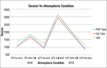
Very often OPGW replaces the earth wire component of power line. So, in order to provide the same desired protection, the OPGW must comprise the proper materials, the appropriate size of wire, and meet the same shield angle criterion. A common practice is to use the existing earthwire or conductor sag as a reference. Moreover, the tensile needs to be within the same level as the earthwire. If tensions are higher, a tower may need to be strengthened.
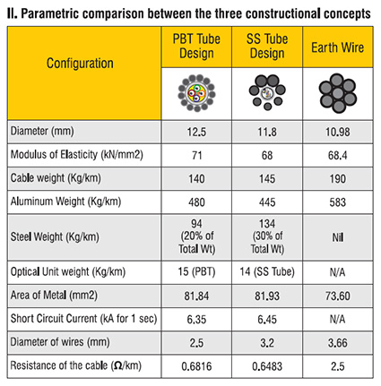
So, Sterlite OPGW is designed to exhibit weight and diameter and the relation between them as close possible to the earthwire.
Conclusion
There is a long history of over 100,000 km of OPGW manufactured with stainless steel buffer tube clad with aluminium. The experience shows this design to provide excellent performance and excellent long term reliability.
The cable withstands very high crush resistance which prevents damage during installation.
Optical fibers are subjected to approximately 50 0C lower temperature during short circuit event.
Very stable optical performance is realized during temperature variation because there is no plastic material in the cable. The thermal expansion/contraction characteristics are nearly unchanged.
Low weight, small diameter and high strength facilitate matching sag of each span. Cable exhibits “self damping” and better endurance during galloping episodes
Our proposed Aluminum Cladded Steel tube design has more metallic cross section area with at least 40% more aluminum content than the PBT tube design.
This design is capable of withstanding higher lightning intensity due to wires size of more than 3mm on the outside.


