Harish Jindal and Asim Jindal,
Kay Pee Dies & Tools, Ghaziabad, India.
Abstract
Wire drawing dies are most vital and crucial part of any wire drawing industry, and for producing quality wire at lowest die cost/ton of wire drawn, quality dies are needed. Improper selection and poor quality of dies adds not only to direct die cost, but more to indirect cost by way of rejections of wire due to poor surface finish, accuracy, and metallurgical properties as well as machine downtime & consequent loss of production. It will be worthwhile to remember that wire making and die making are always a partnership for excellence. Proper and due attention must be paid to this strategic partnership in every wire industry for excellent die management.
Wire Drawing Die Material
Various materials available for making wire drawing dies are Tungsten Carbide (hereinafter called T.C.), Natural Diamond, and Synthetic Diamond, each having its own sphere of application. Almost all wire is either fully or at least partially (from wire rod to a certain size depending upon the material and desired accuracy) drawn through T.C. dies due to their following qualities (this paper concentrates on these dies only due to space constraint):
1. Most cost effective of all three materials.
2. High hardness both at room temperature and high temperatures encountered in drawing operations.
3. Having high resistance against deformation under load.
4. Smaller thermal coefficient of expansion. As a result, variation in size of dies due to rising working temperatures is minimal.
5. Above all, its property to receive and maintain high surface finish up to 1 micro inch.
T.C. dies nibs/ pellets are manufactured by powder metallurgy process from basic raw material Tungsten Carbide with a metallic binder Cobalt. For drawing operations, a nib is required to be hard to wear resistance and tough to resist deformation under load. Since hardness and toughness of any material are inversely proportional, an optimum combination of two properties as per the application is required. For that purpose, T.C. nibs are available in various grades. Different grades of T.C. having hardness of 1400 to 2000 on HV 30 scale and corresponding transverse rupture strength of 1700 to 2800 N/mm square are currently manufactured for drawing operations. These different grades are obtained by varying the grain size of Tungsten carbide and cobalt percentage (hardness increases with decreasing grain size and cobalt content).
Selection of proper grade of nib, in consultation with die manufacturer, is the first step for getting a good die. Grade selection depends upon size and material of the wire drawn and machinery condition. Harder grades are used for smaller sizes of wire and rigid machinery and comparably tougher grades for larger diameter wires, bar drawing and where vibrations or impact loading may be encountered
Work is going on trials and production of T.C.pellets, tough coated with hard powder technology so as to obtain better combination of hardness on the surface and toughness in the core. We can look forward to its commercial application in due course of time.
Selection of Nib Size
Nib cost contributes 50% to 60% of the die cost and proper selection of nib size can help in reducing die cost per ton of wire considerably.
To select the right nib size, following points are considered:
1. Wire sizes and material drawn.
2. Maximum inlet wire/wire rod size used in factory.
The pellet should be large enough to withstand the forces developed in wire drawing and capable of being recut/reground many times to next higher bore sizes. Thicker and harder the wire, bigger should be the pellet size used. Advantage of bigger pellet is that it can be repeatedly recut and reconditioned to next higher sizes. The biggest pellet size to be procured should be the one required for first wire drawing/rod breaking operation.
Many wire manufacturers tend to order all the smallest bore dies in the biggest pellet size under the impression that all these dies will be recut repeatedly to be used in first operation. But there is a catch here, which is generally overlooked. Production obtained from a die increases as the wire size increases because die wear is proportional to length of wire drawn rather than weight of wire drawn, as such thicker the wire higher the weight of wire drawn for the same wear of die. Let me illustrate the same with a hypothetical example of a company producing 1000 tons 12SWG wire per month from 7mm wire rod. The requirement of dies to achieve this production at various stages of reduction shall be as under:
12 SWG -70 (Depending on wire material & permissible tolerances)
8 SWG -50
4 SWG -40
6.5mm/ Rod Breaking – 30 Maximum
When only 30 die in maximum size are needed, why procure all dies in biggest pellet? By ordering dies in mix of pellet size as under, saving up to 30% on die cost can be achieved.
20 Dies in 14 x 12 ISO Standard pellet@ $5 = $ 100
20 Dies in 16 x 13 ISO Standard pellet@ $7.5 = $150
30 Dies in 20 x 17 ISO Standard pellet @ $10 = $ 300
Total = $450
Against 70 dies in 20 x 17 pellet @ $10 = $700
Saving = $250 i.e. 35% of $700 p.m.
Die Profile
Next to grade of carbide, die profile is the most critical factor contributing to die performance. The various component of die profile are as shown in fig.1
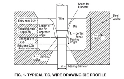
Steel casing: It should be sufficiently big not only to protect the costly T.C. pellet, but also to absorb and pass on the heat and stresses developed during wire drawing process. It is advisable to use the biggest casing which can be accommodated in the die box.
Entry zone: It provides access to lubricants and guides the wire to reduction zone. It should be sufficiently wide to allow free flow of lubricants especially in case of dry drawing. Two types of nibs are currently manufactured, one with Bell Shaped entry zone and one with Wide Angle. Bell shaped entry zone nibs are good for wet drawing to allow smooth flow of lubricant and wide angle entry zone are good for dry drawing since these permit entry of large amount of lubricant into entry zone which gradually enters the reduction zone under pressure.
Reduction zone: The deformation of wire takes place in this zone and the included angle is called reduction angle, which is determined by percentage area reduction and material being drawn. Actual reductions takes place in contact length of wire and die which is about 75 to 100% of wire diameter. Total length of reduction zone should be twice the wire diameter to allow free flow of lubricant to contact zone.
Bearing: It consists of a parallel portion of diameter equal to desired wire diameter (Little less or more depending upon the material being drawn, since hard wire tends to spring back and results in wire size bigger than die diameter, whereas soft wire reduce in size after coming out of die due to drawing forces). The length of this portion is between 30 to 75% of wire diameter, depending upon material being drawn, lubricant and the drawing speed. Longer bearing length increases the die life but results in excessive friction, heat generation, poor lubrication and consequently bad surface finish, residual stresses and work hardening of wire as well as thermal cracking of die, smaller bearings will lead to low die life. This length is decided in accordance with values in fig. 2 coupled with experience in each factory. The bearing portion must be blended with reduction angle with a radius R as recommended and experience.
Exit: The wire exits the wire through this zone. The height of this zone must be sufficient to provide support for the axial mechanical stress produced in drawing process and it should be well blended with end of bearing as back relief to prevent chipping of die and shaving of wire.
Inside profile of die must be mirror polished to reduce friction and improve die life.

Recommended guidelines of die profile for different wire drawing applications are enumerated in the table 1. It must be noted that these guidelines are to be considered along with total area reduction required (From Finish to Start), the number draws of available, power of each machine and above all experience. A word of caution here- percentage of area reduction should be lower than figures arrived as above, in first rod breaking draw due to possibility of ovality and surface defects in wire rods. For Aluminum drawings long bearing lengths are recommended because dies do not wear oversize on bearing but bad wear ring is formed in drawing angle. With large bearing, it will be possible to re-polish the dies number of times in same size.
Die Pass Schedule
Well designed die pass schedule is a must to produce quality wire, but this aspect of wire drawing is sometimes ignored. This schedule is dependent upon:
1. Inlet wire /rod diameter
2. Final wire sizes required
3. Material to be drawn
4. Availability of machines in plant and their drawing speeds.
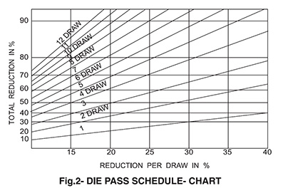
Chart in fig.2 can be used to determine the area reduction per pass, knowing the no. of passes/drafts and total area reduction from starting to finish. Alternately, depending upon area reduction per pass, no. of drafts required can be determined for total area reduction. With percentage area reduction known, different die sizes can be calculated after adjusting for wire slippage.
New Developments in Wire Drawing Dies
Cold rolling of wire
Properzi, Italy have developed machine for die less cold rolling of wire with the help of three shaped rollers driven by chain sprocket arrangement. At speed upto20meters/sec for 3.20mm copper wire to an accuracy of +, – 1%. Machines for reducing 8-10 mm steel wire rod down to 1.5/2 mm are also being developed. It may be sometime before these machines are put in commercial use with some further development and refinements.
Pressure dies
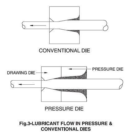
These dies are basically combination of two dies, first of which has a diameter slightly larger than the second (which is of the required wire size ) and lubricant exiting from first die enters the second die at a pressure(hence the name pressure die) which results in lubricant pick up and generation of a residual film in the first draft and preservation of this lubricant film in subsequent drafts as schematically illustrated in fig.3
Rotating die boxes
These die holders house the die in a bronze holder casing that smoothly rotates alongwith drawing die in speed range 4 to 48 RPM around the wire being drawn. Lower speed boxes are used in final pass, to get a good finish on wire and to avoid the friction which may be created in fast rotation of die as well as high drawing speed. For initial passes fast rotating die boxes are used since the drawing speed is lower in these passes. Use of rotating die boxes results in following advantages:
1. Avoidance of ovality in wire and capability to produce high accuracy wire.
2. Uniform die wear and less wire breakage.
3. Longer die life
Adjustable dies
For drawing of square /rectangular wire/ bar in range 4 to 32mm adjustable dies with four interlocking pieces of Tungsten carbide are also available. These pieces can be adjusted to desired size and locked in position.. Due to their high initial as well as regrinding cost, these dies have not yet found popular acceptance.
Importance of Die Cooling
Deformation of wire as well as friction between wire and die generate heat, which increases with increasing drawing speeds and higher reduction. Temperature rise of 60 – 80 degree Celsius for mild steel and 100 – 150 degree Celsius for high carbon wire per draft is normally encountered. Various techniques are adopted to dissipate this heat and cool the wire between two passes. Cooling of die with running water is one such technique being employed successfully since it dissipates heat at the source of its generation. Even though it has been found that this technique removes only 5%of the total heat generated, still its effectiveness and importance cannot be over emphasized due to following reasons.
1. It is the least expensive method of heat removal
2. It increases dies life , and prevents thermal cracking of die
3. Tungsten carbide loses its hardness with rising temperature to the extent of about 5% at 100 degree Celsius 10% at 200 degree Celsius and 30% at 400 degree Celsius. Lower hardness will lead to quicker die wear, abrasion of die and consequently scratching of wire produced.
4. Tungsten carbide nib is usually shrink fitted in steel case and coefficient of thermal expansion of tungsten carbide is only half of steel, as such with rising temperature beyond 200 degree Celsius the pellet may loose its support resulting in its cracking or bursting.
It must be ensured that water does not seep into the lubricant or die which may lead to lumping of lubricant and reduce its flow into die. While starting drawing operation, flow of running water is gradually increased as the die temperature rises and then continuous flow maintained.
Special Considerations for Mechanically Descaled Wire Rod Drawing
Pickling to remove scale and rust and Lime/Borax/Phosphate coating of wire rods for absorption of lubricant has been common practice for over 100 years. With current emphasis on pollution control, world over, more and more units are switching to mechanical descaling of wire rods. Technologically advanced descaling equipments (either continuous or batch process) being very costly, traditional reverse bending descalers are being commonly used due to their low cost and ease of operation. But this process leaves some scale, residual dust and rust on the wire rod. To tackle the problem of these residues, following precautions may be taken:
1. Lubricant should not only be of better quality but abundant flow should be maintained. Use of pressure dies can be useful to achieve this aim.
2. Lubricant powder in die box be stirred regularly for which lube stirrers can be employed, if necessary.
3. Bearing length( especially for first draft) of die be reduced to 75% of that used for pickled/ coated wire rod.
4. Percentage area reduction in the first pass be reduced by about 25% of normal practice for pickled wire rod.
It may also be noted that die life is likely to be reduced by 5 to 10% (more in the first pass) depending upon the quality of descaling and lubrication.
Die Wear
Even ultra hard dies are subject to wear and tear and in absence of proper maintenance, repolishing/reconditioning of dies, they will not be able to withstand thermic and frictional wear encountered during wire drawing and ultimately effect the overall operation and economy of wire drawing plant.
Wear in die is demonstrated by breakdown of lubricant skin on wire and appearance of polished/brightened side of wire. If the drawing is allowed to continue, this brightness will lead to series of longitudinal lines, scrapping and ovality of wire. If we check the die as soon as brightness on wire is spotted, ring formation will be found in the drawing zone. Due to this ring formation particles of carbide are removed which move forward with wire and generally not absorbed by lubricant skin on wire. These carbide particles along with wire particles obstruct the lubricant flow leading to higher drawing pressures heat generation and ultimately die failure.
It is advisable to clean and service the dies at regular interval, as decided by experience and use in the company. Since defective wire coming out of one die will affect performance of all subsequent dies, it is suggested that complete set of dies be changed rather than changing one die, this will also reduce machine downtime if dies are changed as and when worn.
In industry preventive maintenance rather than breakdown maintenance, is common practice similarly for best performance in wire mill preventive change of dies rather than breakdown changing of dies be followed. In technically advanced wire drawing units, whole set of dies are changed at regular intervals (determined by experience and past records) rather than waiting for any defects to develop in wire or die.
Recutting of Dies
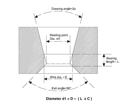
A worn out die recut to exacting parameters of die profile, will perform as well as a new die. The steps to be followed in recutting of dies are as under:
1. Lap the reduction zone to required size, correct the entry zone and blend the two.
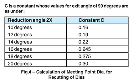
2. From the back side of die, correct the exit angle and maintain Diameter d1, which can be calculated by referring to fig. 4.
3. Make the bearing portion with a parallel pin with starting taper of 3 degree to desired wire size D leaving 0.05mm margin for polishing of die.
4. Blend bearing with exit.
5. Diamond polish the die from front side, blending the bearing with reduction zone and maintaining the correct die size.
C is a constant whose values for exit angle of 90 degrees are as under :
Die Inspection
The best method of checking dies is with DIE PROFILOMETER, which can accurately check die profile , size and surface finish. These profilometers are costly and not all units. Need and can afford it. With experience and practice, dies can be inspected visually with small investment.
1. Magnifying glass or microscope for general die profile and surface finish.
2. Angle Pins of required degree for drawing angles.
3. Plug gauges for bearing length.
4. Small hole gauges for checking bore dia above 2 mm.
5. Plug gauges or drawing of soft wire with wire puller for checking bore dia below 2 mm.
Die Inventory Management
Ideally any wire unit should purchase only finish size dies required for final wire and all other sizes manufactured in house/ on contract basis by recutting worn out dies. All the new dies issued from stores should be serially numbered and stamped along with company name. Number wise record of dies be maintained in a die history card separate for each die, which should record:
1. Date of Issue
2. Dates and Sizes of re-grinding together with output in each size
3. Machine Number for which it has been issued in case of each size
4. Date and reason of return of die to stores
Above records may add some expenses but these will be more than offset by reduction in die cost, performance evaluation of different brands of dies and control of pilferage and duplication of dies.
Training and Seminar
Basically selection, recutting, inspection, management of dies are matters of experience and training coupled with the guidelines enumerated above. To impart this training, seminars and workshops for shop floor personnel should be conducted in-house or by an outside consultant in the language and terminology of shop floor.


